You use the toolbar at the bottom of the board: Wire to run conductors, Meter to test, then Run Simulation to power it up. New to Dakota? Press Walkthrough in the sidebar for a guided 5-minute sample lab.
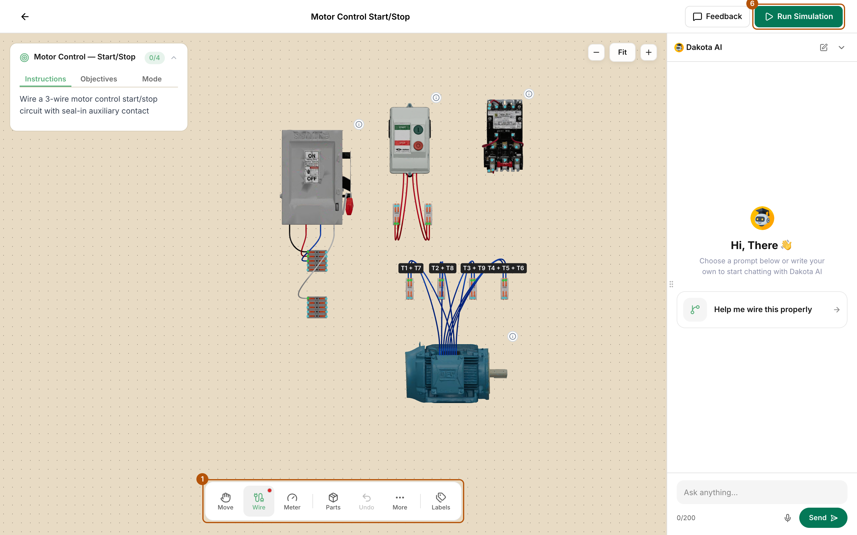
Steps
-
Wire. Press Wire (or the
Wkey). Tap one terminal, then tap the terminal it should land on. To back out halfway, press Cancel this wire. -
Pick a colour. Press Wire again to open the menu and choose a Wire Color. Some labs also show a Gauge column for wire size.
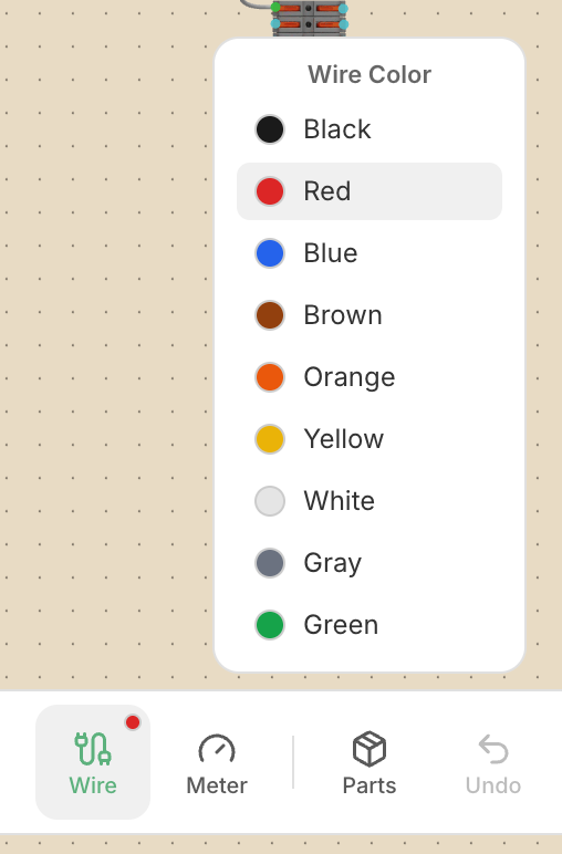
Press Wire again to choose a wire colour and, in some labs, a wire size. -
Fix a mistake. Press Undo to take back your last step. Or tap a wire and press the bin icon (Delete this wire). To start over, open More, then Reset Wiring (this can’t be undone).
-
Check terminal names. Press Labels to show or hide terminal names.
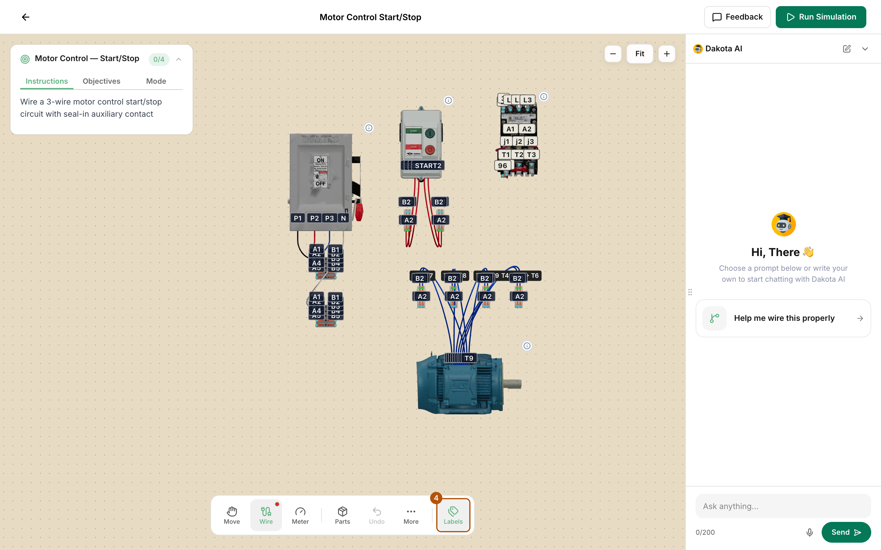
Press Labels to show or hide terminal names. -
Test with the meter. Press Meter (or the
Mkey). The Multimeter card opens. Tap two points to check continuity. V (voltage) and A (current) only work while the simulation is running. For current, tap a wire to clamp it. Press Reset probes to start a new reading.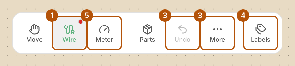
Wire (1), Meter (5), Undo (3), More (3) and Labels (4). 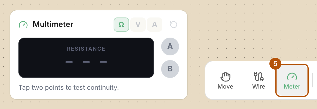
Press Meter, then tap two points to check continuity. V and A work while the simulation is running. -
Run it. Press Run Simulation at the top right. Use Simulation Controls to work the gear on your board (for example Main Power, START and STOP), and watch the status rows change.
-
Go back to wiring. Press Exit Simulation.
Moving around the board
- Mouse: scroll to zoom, double-click a part to zoom in, click and drag a part to turn it. Use + and - to zoom, and the reset button to go back to Fit.
- Tablet or Apple Pencil: slide one finger to move around, tap to act, press and hold a part then slide to tilt it, and pinch with two fingers to zoom. There’s no double tap.
- Phone: turn it sideways. The board needs the long edge of your screen.
Common problems
- Run Simulation is greyed out. Draw at least one wire first.
- “Short Circuit Detected.” The breaker tripped. Press Return to Wiring and fix the wiring.
- The meter’s V and A buttons don’t work. Run the simulation first.
- I added parts but nothing appeared. In the Parts menu, pick your parts, then press Add to Canvas.